The CNF has three contact lithography tools: an ABM, Suss MJB4 and a Suss MA/BA6. The EV620 and the Karl Suss are capable of doing front side and back side alignment while the ABM is mostly for front side alignment. Careful planning of your design and alignment scheme is important for success.
The first lithography level is simply aligned with the wafer flat, as no previous pattern is on the wafer. The first mask should include marks for alignment of the next lithography level. When printing the second lithography level, the operator uses microscopes to look through the second level mask and align marks on the mask with the previously printed marks on the wafer. For that alignment to be accurate, the marks on the mask must be clear field or bright field in nature. That means that the mark on the mask is dark chrome with the glass around the mark clear. If that is not the case, the user will not be able to see the wafer underneath for alignment.
The CAD files provided for the alignment marks include both dark field and bright field versions of the marks. Most users will need to use the bright field marks on layer 2, but the dark field marks are also provided on layer 3 of the CAD file. For designs with more than two mask levels, generally a separate set of marks is needed for each pair of masks to align. Alignment marks for all masks can be printed with the first mask, or each mask can print only the alignment mark for the level immediately after it.
The photolithography staff can recommend which method to use based on your alignment needs.
Placement of Alignment Marks
Proper placement of the alignment marks is required to ensure that they will be visible on the tool and allow accurate alignment. Two marks are used, generally placed on the horizontal axis (at Y = 0 in the CAD) near each edge of the wafer . This is with the wafer flat at either the top or the bottom of the CAD. Although it is recommended to place the alignment marks on the wafer center (Y=0), all of our contact tools will work with marks approximately 1 cm above or below the middle. By placing two marks, both X, Y, and Theta (rotational), error can be reduced. When performing front to back alignment on the MA/BA6, you must be careful that the marks are visible within the windows of the wafer chuck. Contact the MA/BA6 tool manager for further details.
Each of the following CAD files has one alignment mark in it. Therefore, two copies of it must be placed on the design (@ X = ± some amount, Y = 0). The CAD file has several layers in it for the different mask levels. Please see the included README.TXT for a description of the file and layers.
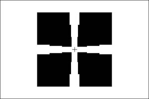
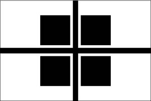
Standard Contact Alignment Mark
This mark can be used on all tools and provides the most accurate alignment. It can also be used for backside alignment on the MA/BA6.